•Learn the different ways how to create Nodes in VERTEX
•There are various options how to combine Parameters from different Properties in a single Node
•Connect Nodes and enable a data flow between them, disconnect them or just deactivate the data connection
Create a Node
VERTEX offers you different ways to create a new Node into a Node System. All ways are deeply integrated into the VERTEX UI and adapted to the workflow of our software
Drag an item from Project Explorer to the Node System Editor
Create a new Node by simply drag and drop an item from Project Explorer to a Node System Editor:
•Select an item (e.g. Content, a System, a Surface) in the Project Explorer
•Drag this item with your mouse to the Node System Editor
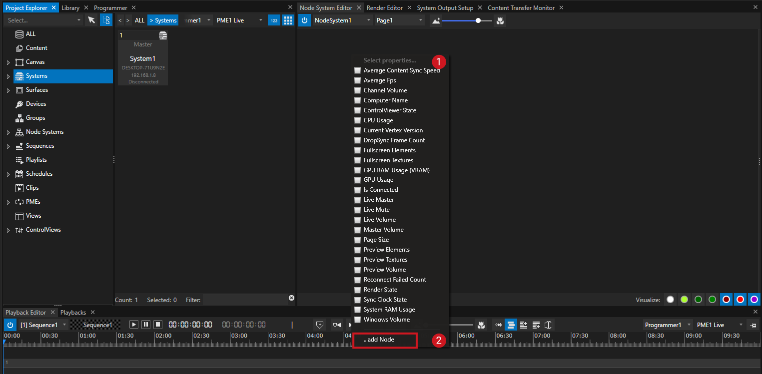
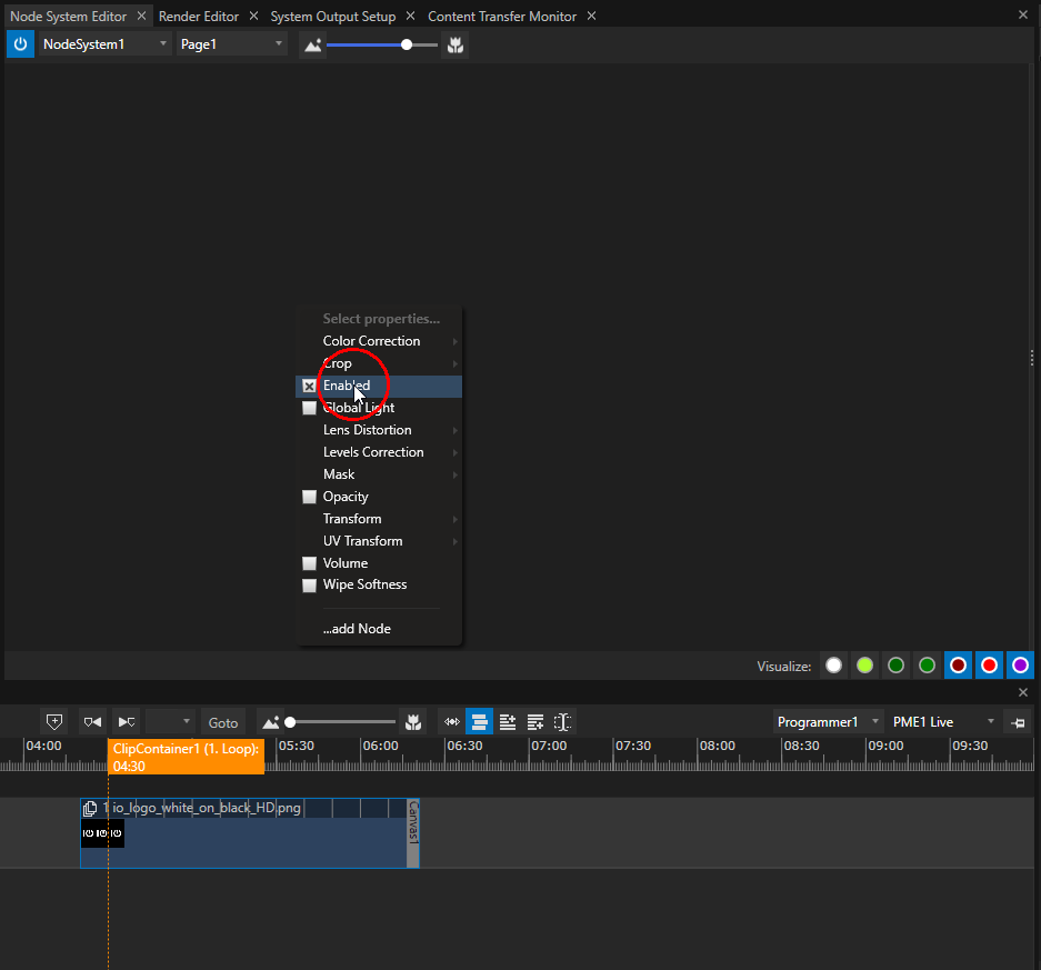
•A context menu opens where you can choose from a list of all available properties,
•Select one or multiple properties from the list (1)
•Confirm your property selection with "Add Node" (2)
•A new Node with the selected properties is created
Drag Properties from Inspector to the Node System Editor
•Select an item
•Go to the Inspector
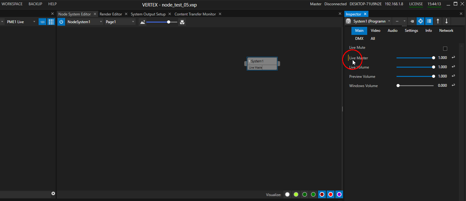
•Select a property in the Inspector.
Like you may known from Wiring or Triggering, properties that could be used are marked with a yellow vertical line.
•Drag this property with your Mouse to the Node System Editor
•A new Node with the selected property as parameter is created
Combine different properties and create custom Nodes
VERTEX gives you the option to create custom Nodes that combine Properties from different items.
•Create a Node with properties from a first item (e.g Canvas 1)
•Select a second item (e.g. Canvas 2)
•Drag a property of this item from Inspector to the already created Node
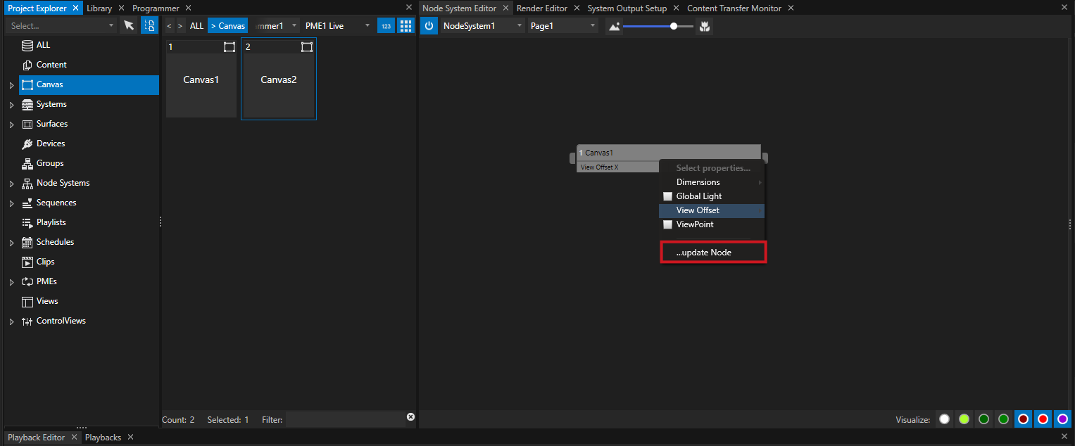
•Or drag the item from Project Explorer to the already created Node. When the mouse button is released, a context menu pops up where you can select the properties you want to add.
•Select "update Node"
•The already existing Node is updated and converted to a Node that combines properties from different items (e.g. Canvas 1 and Canvas 2)
 Show full property source of a Node Parameter
For a better and cleaner overview - the property fields of a Node in the Inspector show reduced information: They only shows the property name but not the full origin. When working with combined Nodes, a tooltip displays you the whole property source.
To show this tooltip, hover with your mouse over the parameter field into Inspector or over the parameter field of the Node into Node Systems Editor.

Toolitip with full source of a Parameter property
Drag a Clip Container to the Node System Editor
•Select a Clip Container into Playback Editor
•Hold CTRL + SHIFT on your keyboard
•Drag the Clip Container with your mouse from the Playback Editor to the Node Systems Editor (continue to hold down CTRL+SHIFT)
•Release the mouse button and the keys and a property selection menu is displayed
•Select the properties you want to have as parameters for your Node
•Confirm with "Add Node" on the bottom of the context menu window
Drag and Drop from any other Editor
Creating Nodes via drag and drop is also possible for other some other VERTEX Editors.
Hold CRTL and SHIFT and drag e.g. a Control from the Control View Editor to the Node System Editor.
Or Drag an DMX-Routing from the DMX-Routing Editor to the Node Systems Editor
 Devices and Nodes
Remember that you first have to add Devices from the Library to your Project.
Once added, you are able to drag them from the Project Explorer to the Node System Editor.
Creating Nodes directly out of the Library will not work.
Connect and Disconnect Nodes
To enable a data exchange between your nodes, they have to be connected with a Connection Line.
Without Connection Line there is no data flow between an output of a Node and the input of another Node.
Connections are elementary for a Node System to work.
Connect
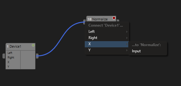
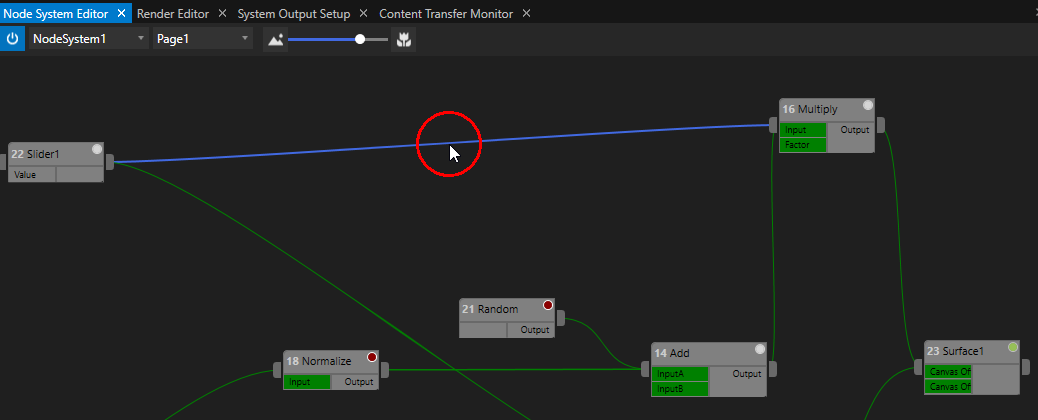
•Select the Output pin on the right side of a Node and move your mouse
•A blue Connection Line is drawn
•Drag the mouse with the blue Connection Line to an Input pin of another Node (on the left side of a Node)
•When you have reached the Input pin, a context menu opens:
oSelect the Output from the first Node into this context menu and
othen select the input or condition of the target Node
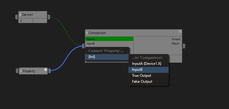
•When the connection is successful, the connection line turns into green color and the Input Parameter of the second Node is highlighted green
Disconnect
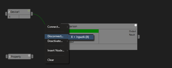
•Right-Click with your mouse on a connection line
•The context menu opens
•Select "Disconnect..."
•Select the Connection you want to disconnect
A single Connection Line and more than one data connection
No matter how many Parameters are wired between two nodes. there is always only one Connection Line. If there is more than one parameter connected, the disconnect menu offers you several options. If there are e.g. two data connections between Nodes and only one of this connections is disconnected, the green Connection Line is of course kept
Insert a Node
•It is possible to insert a Node between two already connected Nodes.
Steps
1.Right-Click with your mouse on a connection line between two nodes
2.A context menu opens
3.Select "Insert Node"
4.Select a Node you want to insert
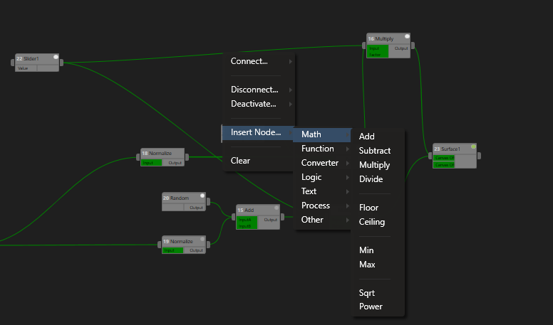
•The selected Node will be inserted between the two initial Nodes
•Depending on the inserted Node type, another context menu opens where you can assign the values to the input parameters of the new and inserted Node

Depending on inserted Node type: Last step is to connect the data to the inputs of the inserted node. After a new node is inserted between, a context menu to assign opens
Deactivate or activate a Data Connection
To stop a data flow between two Nodes, you are able to deactivate a data connection.
Of course you are also able to activate connections again
Deactivate
•Right-Click with your mouse on a connection line
•The Context Menu opens
•select "Deactivate..."
Deactivated Connections are gray instead of green
You can recognize deactivated data connections by the gray color of the connection line.
If the connection is deactivated, no data flows between the two Nodes.
Activate
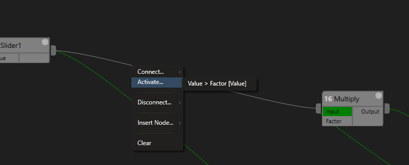
•Right-Click with your mouse on a deactivated an gray connection line
•The Context Menu opens
•Select "Activate.."
•Select the Connection you want to activate
Composite Node
VERTEX offers you the possibility to build Nodes that contains a logic of other Nodes.
We call this kind of Nodes "Composite Nodes". You are able to built your own nodes as a subcomposition of other nodes. You can work them like normal Nodes and use them in your Node System.
Read more about here: Composite Node
Advanced:Target Systems for Node Systems
•If working with multiple Systems into a Project, you can define on which of this Systems a Node System should be executed
•By default, a Node System first is only executed and running on Master
•If a Node system should run on multiple Systems into your Project, you can define this with the Target Systems Tab
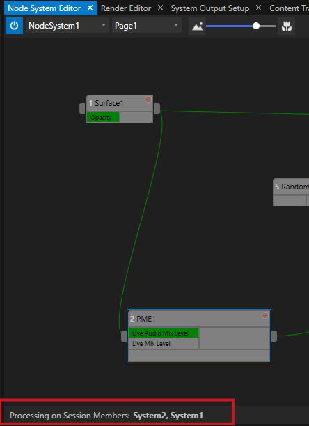
•The Node System Editor displays on which Systems your Node System is currently executed and running
Define Target Systems
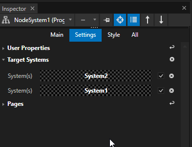
•First switch to the Advanced Mode of The Inspector
•Select a Node system into Project Explorer
•Open the "Target Systems" tab into the Inspector
•Drag a System from the Project Explorer to the Target Systems Tab
•Repeat the last step for all Systems on which you want to run the Node System
There is an information into Node Systems Editor on which Systems of your Project your Node System is currently processed: